| 1 | Physically connect the controller
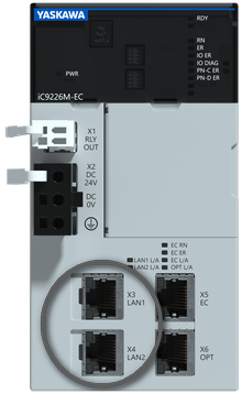
Connect the controller to the LAN in which your engineering PC is located via one of the controller's Ethernet ports. Do not use its EtherCAT port(s) as they do not support the network scan function used in this procedure.Via the Ethernet ports, the controller can communicate with iCube Engineer (programming and remote maintenance of the controller), its web-based management (WBM) can be accessed and the OPC UA communication is handled.
(If required, these ports can also work as Profinet ports. This way, the controller can be used in a Profinet system as a Profinet IO controller or, in a higher-level Profinet system as a Profinet I-Device. For this, the Profinet functionality must be activated in the WBM and licensed.)
 Example: Ethernet ports X3/X4 of the iC9226M-EC controller Example: Ethernet ports X3/X4 of the iC9226M-EC controller
|
| 2 | Create a project
Create a new project by selecting a controller-based template or sample project on the Start Page.Alternatively, choose 'File > New Project' to create a project with an empty PLANT. |
| 3 | Define the project IP range
- Double-click the 'Project' node in the PLANT.
- Open the 'Settings' editor and select the 'IP Subnet' category.
- Specify the 'IP range' settings.
Setting the project IP range is not mandatory. However, you will receive a warning later if the controller has an address outside this range. |
| 4 | Scan the network for a controller
Procedure: scanning the network for an iC9226M-EC controller when starting with a controller-related template
Note
For a network scan as described below, it is not necessary to manually establish a communication connection using the 'Connect' command (controller context menu in the PLANT) before the scan. This is done automatically by iCube Engineer. |
- Double-click the 'Project' node.
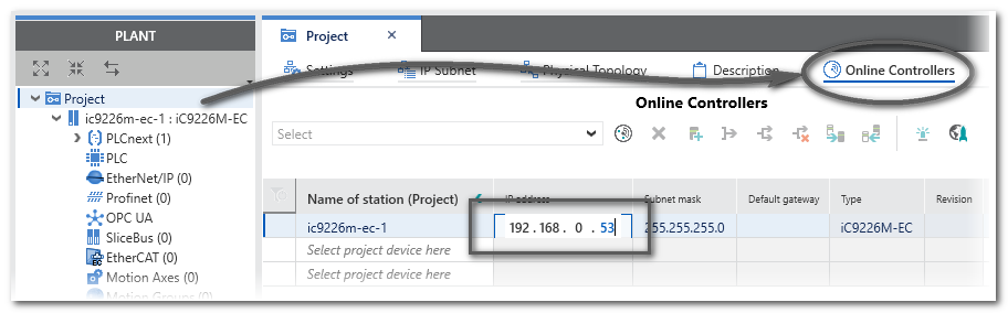
- In the editors area, open the 'Online Controllers' editor (see (1) in the figure below).
- In the drop-down list (2), select the LAN adapter of your computer which is connected to the controller network to be scanned.
- Click the 'Scan the network' button (3) on the 'Online Controllers' toolbar.
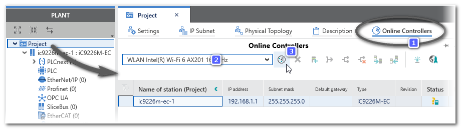
The network is scanned and found controller devices are listed in the table. The assignment of the project device and the found online device is made automatically after scanning because you have used a controller-based template (i.e., the project controller name and the online controller name are identical).
Any other scanning result as described in the procedure?
If scanning does not produce the result described above, refer to the procedure " Scanning the Network for a Controller (controller-based Template)". Possible scenarios are:
- The assignment of project and online device is not done automatically due to one of the following reasons:
The scanned controller and the project controller differ or multiple controllers are found on the network.
Differing devices are indicated by the status icon  . . If no automatic assignment is made, select the desired controller (online device) in the drop-down list in the 'Name of Station (Project)' field in the leftmost column. This way, the IP address of the field device is transferred to the project (and not the other way around).
- The communication connection 'Status' switches to 'Warning' because the communication settings of the scanned controller do not match the (default) communication settings in your project (which are predefined in the used project template).
A warning is indicated by the status icon  . .
|
| 5 | Configure controller IP address
If the IP address of the controller is not as required, you can define it in the PLANT:
If you work online, i.e., you have scanned the network:
Modify the IP settings of the scanned controller directly in the 'Online Controllers' editor ('Project' node).When changing a field in the left part of the table (on project side) and confirming the modification with <Enter>, the new setting is automatically written to the device (shown on online side).
Example: modifying the scanned IP address of an iC9226M-EC controller
If you work offline and you have structured the PLANT via the station editor:
The IP settings are assigned according to the IP range set for the 'Project' node. You can then modify individual device addresses via the 'Settings' editor of the controller. |
| 6 | Scan the network for EtherCAT slave devices
Now that the controller is available in the PLANT, you can scan the network for EtherCAT slaves.
Procedure: performing an EtherCAT bus scan
Note that the EtherCAT bus scan is only available while the controller is not connected to iCube Engineer.
Right-click the EtherCAT node in the PLANT (which represents the bus master) and select 'EtherCAT Bus-scan' from the context menu.
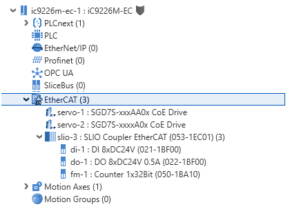
EtherCAT slaves found by the scan are automatically inserted into the PLANT under the 'EtherCAT' node. In addition, the slaves are inserted into 'Device List' editor (station editor) of the EtherCAT master.
If a bus coupler is found, the I/O modules connected to it, are also inserted (under the coupler node and into the coupler's station editor).
Devices are inserted as 'unknown' if they are not contained in the 'Network' category of the COMPONENTS area. Possibly, the corresponding device libraries are missing in your project and have to be added.
If a servo slave is detected in the network, the corresponding axes are added automatically under the 'Motion Axes' node and the axis-ref variables are made available in the project.
Example: The bus scan has detected a servo drive and an EtherCAT bus coupler with three connected modules.
It is also possible to insert devices manually via the station editors. |
| 7 | Connect iCube Engineer to the controller
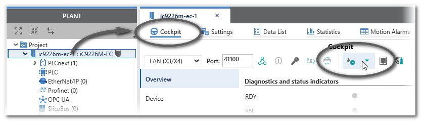
- Double-click the controller node in the PLANT and open the 'Cockpit' editor.
- In the Cockpit, click the 'Connect to controller' button on the toolbar.

The authentication mask appears. Enter the user name of the administrator user role as well as the relating password and press <Enter> to log on. On delivery, the default user with administrator rights is admin. The password is printed on the front of the controller.
|
| 8 | Use the EtherCAT Online Functions to analyze the bus, that is to say, inspect the states of the EtherCAT master and the slaves.
Example: EtherCAT Online Functions for sample slave devices/modules
The diagnostic function shows the master and each of the found devices in the Op state:
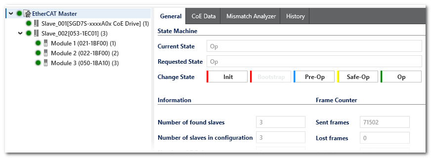
Refer to the help chapter "EtherCAT Online functions" for details. |
| 9 | Define security settings via WBM (recommendations)
- Access the Web-based Management (WBM) by clicking the following icon on the Cockpit toolbar:

The login page to the controller's WBM appears in the default web browser.
- Logon to the WBM with the admin user name and password.
In the WBM, open the 'Security' category and adapt the settings.
Further Info
Details on the possible settings mentioned below can be found in the respective controller user manual. |
Activating and configuring the internal firewall on the controller (deactivated on delivery)
- Open the 'Firewall' page.
- You can activate the firewall temporarily or permanently:
Temporary activation: Set 'Status = Start' and click 'Apply' (lower screen border). The firewall is activated immediately and remains active as long as the controller is not restarted.
Permanent activation: Mark the 'Activation' checkbox and click 'Apply' (lower screen border). The firewall is activated immediately and remains active even after a controller restart.
- Set the basic filter rules using the options in the 'Basic Configuration' section.
The currently set firewall configuration can be displayed by clicking the 'Show Rules' button (section 'System Status' at the beginning of the page).
Adding and defining user roles in addition to the default admin user
- Open the 'User Authentication' page.
- Click 'Add User', enter the desired user name and password and confirm.
- Click 'Modify Roles' for the newly added user.
- Mark the checkbox for each access right to be granted for the user (multiselection is possible). The meaning of the access rights provided for selection are described in the controller manual.
Also observe the help chapter "Network Security: Authentication with User Role and Password" for details on the implementation in iCube Engineer.
Adding a controller certificate
- Open the 'Certificates Authentication' page.
- On the 'Trust Store' tab, you can add trusted certificates and revocation lists of communication partners. Communication partners must authenticate theirselves using these certificates when establishing the communication connection.
- On the 'Identity Store' tab, you can create and add certificates.
It is recommended to personalize the secure communication connection between the controller and iCube Engineer by adding your specific certificate here. After (creating and) adding your own certificate, you must also add the certificate in the trust store of iCube Engineer.
For further information, refer to the help chapter "Network Security: Certificates enable Secure Connection" for details on the implementation in iCube Engineer as well as to the controller manual.
|
| 10 | Configure the controller via WBM
- Profinet functionality
Your controller is connected to iCube Engineer via an Ethernet port. If you use the device as Profinet IO controller or, in a higher-level Profinet system as a Profinet I-Device, the Profinet communication is also handled via these Ethernet ports. To use the Profinet functionality...
- make sure that the separate and paid license is installed in iCube Engineer. To check or add a license, open the WBM page 'Administration > License Management'.
- it must be activated under 'Configuration > System Services'. Mark the corresponding checkbox.
- Adapt further controller parameters on the different pages of the 'Configuration' category.
Further Info
Details on the possible settings can be found in the respective controller user manual. |
|
| 11 | Parameterize devices via iCube Engineer
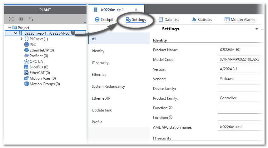
Parameterize the devices in the PLANT. For that purpose, double-click each device node in the PLANT to open its properties in the editors area. To parameterize safety-related devices, you have to be logged on to the Safety-related Area.
Example: Setting the properties of an iC9226M-EC controller
|
| 12 | Add Libraries or Import IEC Types
If required:
|
| 13 | Develop the application code
- Create POUs in the respective category in the COMPONENTS area:
'Programming > Local > Programs' and 'Functions and Function Blocks'.
Object-oriented function blocks with methods are supported.
- Define data types (folder 'COMPONENTS | Programming > Local > Data Types').
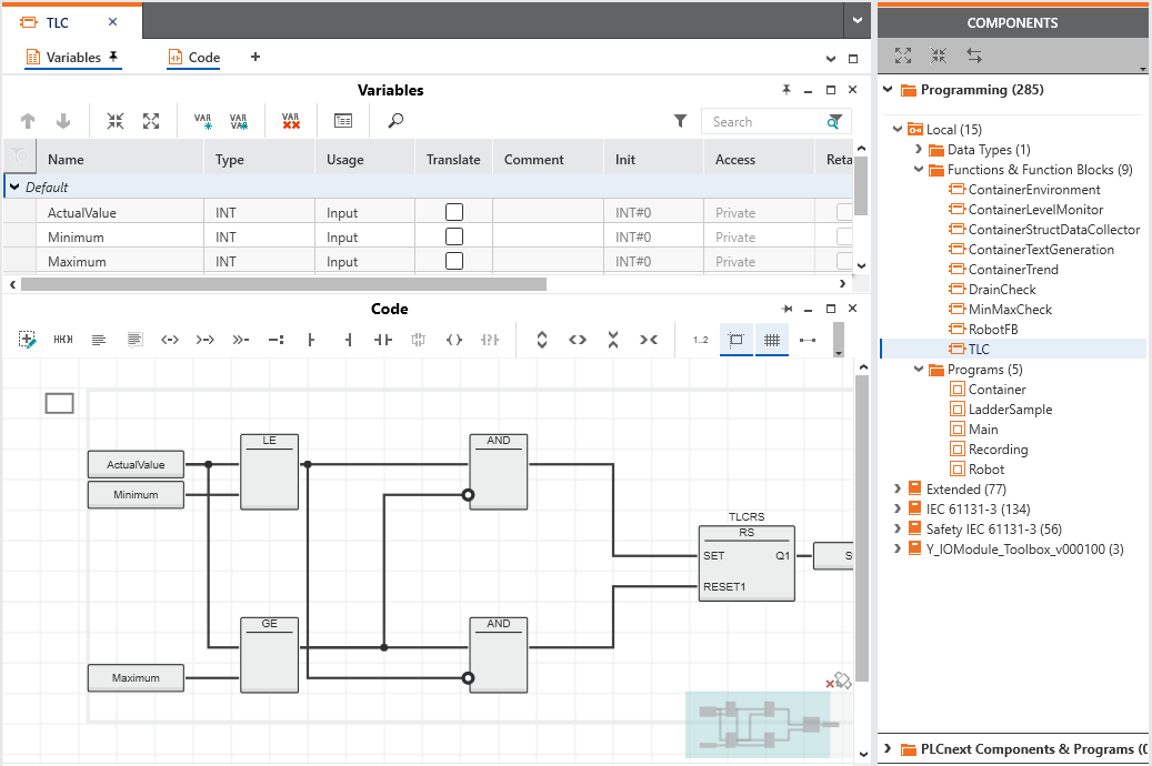
- Program the POUs in one of the IEC 61131-3 programming languages FBD/LD, ST or SFC.
If a Safety PLC is included in your project: Safety-related code has to be written in SNOLD code worksheets. For that purpose, you have to be logged on to the Safety-related Area.
- With a iC9200 Series controller, you can declare IN and OUT ports in program POUs instead of or in addition to resource-global variables.
Via these ports, communication is possible with non-IEC 61131-3 programs you have included as libraries. See section "Integrating externally developed non-IEC 61131-3 programs ..." for details.
- GDS Port List assignments
With a iC9200 Series controller, IN and OUT ports can be assigned to each other in the GDS Port List of the 'PLCnext' node. This also includes ports provided by non-IEC 61131-3 programs you have included as libraries. The assignment of ports enables the data exchange between programs.
- If a Safety PLC is included, you can create exchange variables which enable the communication with the standard (non-safety-related) machine controller.
While programming, typical programming errors are detected by the automatic background check. (Note that the
error list
is only updated after completing the compilation.)
Example: POU in FBD
|
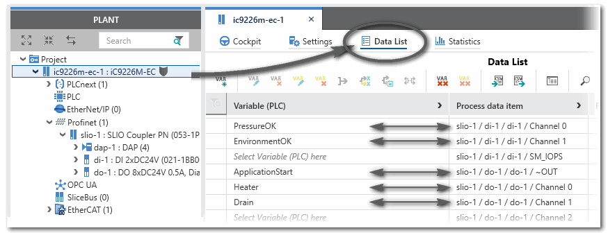
| 14 | Map I/O signals (process data items) to IEC variables
Assign process data items (signals coming from/written by I/O terminals) to global IEC 61131-3 variables. By defining this mapping, the application is able to read input and write output terminals. The assignment can be done in the Data List editors of, for example, the 'PLC' node or I/O device involved.
Example: Signal mapping - assignment of global variables to process data items in the controller Data List
|
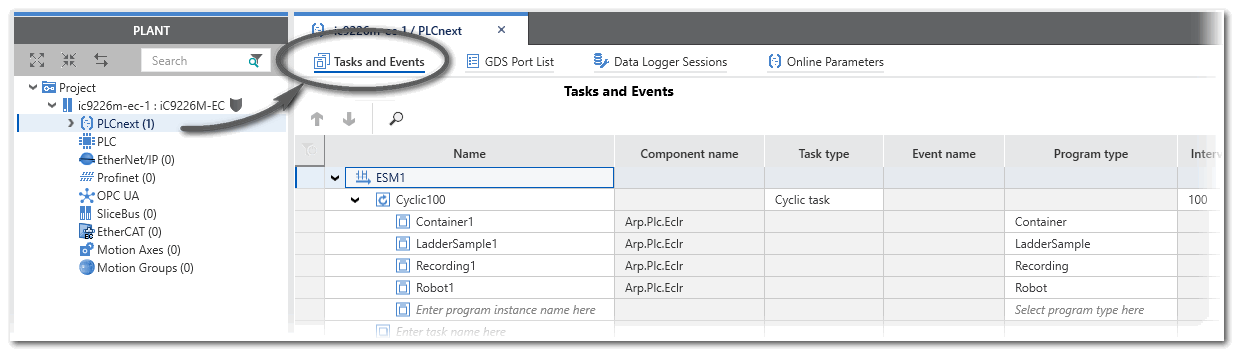
| 15 | Define the task scheduling and instantiate programs
Example: Task configuration for an iC9226M-EC controller
Note
If a Safety PLC is included in your project, the PLCnext 'Tasks and Events' editor contains a SafetyProxyTask which has been created automatically. This SafetyProxyTask triggers the execution of the Safety PLC. This task cannot be edited or deleted.
Refer to the topic "Safety PLC Runtime Configuration" for details. |
|
| 16 | OPC UA configuration
iC9200 Series controllers include an
OPC UA Server
which is integrated in the controller besides the machine controller runtime.
The controller can also be configured and used as OPC UA Client.In addition, iC9200 Series controllers with a firmware version 22.0 or newer support the OPC UA PubSub (publisher/subscriber) communication model.OPC UA-related settings can be done in the editors of the 'OPC UA' PLANT tree node. |
| 17 | Startup the application
Execute the 'Write and Start' command to build the project image (compile the project), write it to the controller and run the application. The 'Write and Start' command is available in the context menu of the controller node (PLANT) and in the 'Cockpit' editor. To open the 'Cockpit', double-click the controller node in the PLANT and click 'Cockpit' in the editors area.
 |
| 18 | Debug the application and perform a function test
Perform a function test after the successful controller startup. To support you in this, iCube Engineer provides the following features:
Note
The test of the application in
debug mode using debug commands, the WATCHES window and LOGIC ANALYZER may not replace the proper function test using I/O devices/sensors/actuators under any circumstances. The test in debug mode may only be performed in addition to the standard function test, as a preliminary test, for example. |
Further Info
Refer to the chapter "" for details. |
When eliminating errors, you can use the command 'Project > Rebuild' to build the entire project without writing it to the controller. |
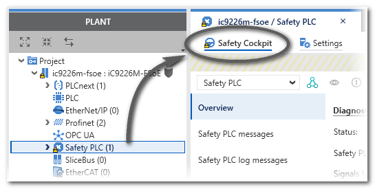
| 19 | Startup the safety-related application
If a Safety PLC is included in your project, it can be controlled completely independent of the standard (non-safety-related) controller. For that purpose an own 'Safety Cockpit' is provided. Here, you have to perform the same steps as for standard machine controller: However, it is possible to write and start the safety application together with the standard application. For that purpose, the commands 'Write and Start Project (incl. Safety)' (with and without project sources) are available in the Cockpit and the PLANT context menu of the standard controller. Instead of explicitly writing and starting only the safety application, you can use these commands to handle standard and safety application with one common command.
Note
The default password for the safety-related area for projects based on a Safety PLC project template, for example for iC9226M-FSOE controller type, is "safety". |
- 'Write and Start' the safety-related application to the Safety PLC (in the Safety Cockpit or via context menu of the Safety PLC).
- Use the monitoring and debugging tools for performing a function test.
Example:
 |