Setting the Controller IP Address
For Profinet, the name of station (device name) is the leading identification characteristic. Therefore, there is usually no need to modify the IP address if the IP range specified in the 'Project' settings is free in your network.
If required, you can modify the IP configuration of a controller in the following ways:
- Via the 'Online Parameters' editor (only for accessible iC9200 Series controllers)
- Via the 'Online Controllers' editor (while the network is accessible)
- Via the 'Settings' editor of the controller
- Via the controller's Web Based Management (WBM)
- Using an ad-hoc IP address instead of project-defined address: Instead of the IP address defined in the controller settings, you can also connect to a controller with any other IP address without having to change the IP address in the project settings and rebuild the project.
| Note
IP address of redundant controller Even if you are realizing Profinet System Redundancy in your application, the PLANT contains only one controller device. The second controller is not visible in the PLANT. The IP address of the second controller can be set after configuring the controller contained in the PLANT. Refer to the help chapter "Profinet Redundancy ×‣ Profinet System Redundancy (SR) ×" for details. |
| Note
A Safety PLC integrated in a controller device does not have an own IP address. |
IP settings via 'Online Parameters' editor
The 'Online Parameters' editor is available for iC9200 Series controller types. The parameters contained in this editor are defined in the device description file. The editor allows to read parameter values from and write values to the device.
- Connect to the controller and login with a suitable user role. It is not necessary to switch to debug mode.
- Double-click the 'PLCnext' node.
In the editors area, open the 'Online Parameters' editor and select the category 'LAN'. - Edit the configuration in the section 'LAN'.
- Click the icon toolbar command
 to write the modified values to the device and apply them.
IP settings via 'Online Controllers' editor (while controller is accessible)
If the controller is connected and reachable via the 'Online Controllers' editor (e.g., after scanning the network), you can set the IP configuration as follows:
| Note
For writing the IP configuration to the machine controller as described below, it is not necessary to manually establish a communication connection using the 'Connect' command (controller context menu in the PLANT) before the scan. This is done automatically by iCube Engineer. |
- Double-click the 'Project' node.
In the editors area, open the 'Online Controllers' editor.
Make sure that the correct LAN adapter is set which is connected to the controller network. - In the devices list, edit the configuration of the controller (e.g., the IP address) on project side.
- Press <Enter> to confirm the modified data and to write the new setting to the device (shown on online side).
 Example...
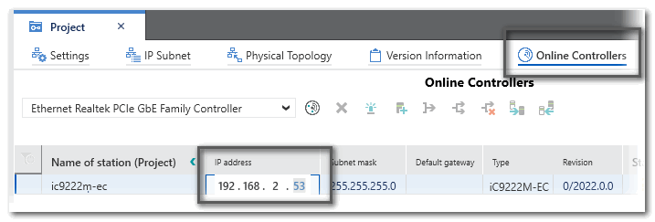
IP settings via the 'Settings' editor of the controller
If the network is not accessible, you can edit the IP configuration of a device in its 'Settings' editor. The modifications are applied, when writing the project to the controller with the matching IP address the next time.
When inserting a controller or bus device into the PLANT manually, an IP address within the specified project IP range is automatically assigned (provided that an address is free). In the most cases, the automatically assigned address in the project will not match the current IP address configuration on the device (which is either the preset IP address after unboxing/resetting the device or an already configured address). The IP settings in the project can be adapted to the IP settings on the hardware.
- In the PLANT, double-click the device node to open its properties.
- Open the 'Settings' editor and select the parameter category 'Ethernet'.
- Depending on the controller type there may be two IP-related settings areas. You must specify the IP address according to the port to which the LAN cable is connected to your controller.
Enter the desired IP settings and confirm each setting with <Enter>.
Observe that the entered individual IP address is within the specified project IP range. Otherwise, a corresponding error message appears in the MESSAGES window, category 'Error list'.
| Further Info
For further alternatives for an IP address assignment, consult the PLCnext Info Center and the device manual. |
IP settings via the controller's WBM
The IP address of the controller can also be set via the Web Based Management of the controller. The WBM can be accessed via the controller Cockpit toolbar.
- Double-click the controller node in the PLANT and open the 'Cockpit' editor.
- In the Cockpit, click the 'Connect to controller' button on the toolbar.

The authentication mask appears. Enter the user name of the administrator user role as well as the relating password and press <Enter> to log on.
On delivery, the default user with administrator rights is admin. The password is printed on the front of the controller.
- Access the Web-based Management (WBM) by clicking the following icon on the Cockpit toolbar:

The login page to the controller's WBM appears in the default web browser.
- Logon to the WBM with the admin user name and password.
- On the left, select the 'Network' page in the 'Configuration' category.
- Define the IP addresses for the available ports and, if required, parameterize the interfaces using the available parameters.